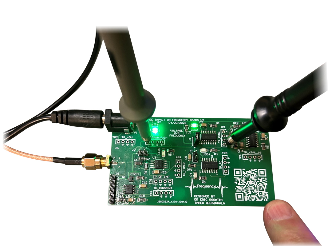
Join Teledyne LeCroy and Professor Eric Bogatin for this series of 30-minute webinars that describe how to design, build, test, measure and debug your assembled printed circuit board. These webinars serve as a springboard for further learning. Each topic will be explored further through a series of videos and coursework through the Teledyne LeCroy Signal Integrity Academy, available soon.
Part 1: Design it Right the First Time – Practical PCB Design and Layout Tips
Available On-Demand
Aired February 8
In this webinar, Eric describes cautions about use of reference designs, describes layout tips to optimize your design for connectivity, signal integrity, assembly, test and bring up, outlines features to reduce switching noise between signals and power rails, and details common problems to watch for.
Part 2: Mastering the Oscilloscope for Signal and Noise Measurements
Available On-Demand
Aired March 14
In this webinar, Eric describes using an oscilloscope in the most effective way possible by minimizing the noise from measurement artifacts and using best measurement practices to optimize SNR. Eric will describe common do’s and don’ts, how to optimize the signal into the oscilloscope, measuring signals correctly, and much more.
Part 3: Building a Prototype PCB and Making Tradeoffs
Available On-Demand
Aired April 11
In this webinar, Eric describes building a solderless breadboard version of a PCB to reduce schedule delays, increase confidence in the design before it is sent for assembly, and gain insight into what debug features to add.
Part 4: Understanding the Function Generator and Using it Properly
Available On-Demand
Aired May 9
In this webinar, Eric provides a brief intro to using a function generator and understanding its output impedance by measuring its Thevenin voltage and its Thevenin resistance. These two figures of merit are compared as settings of the function generator are changed.
Part 5: Using the Oscilloscope to Measure Loop-to-loop Crosstalk
Available On-Demand
Aired June 13
In this webinar, Eric describes how to measure the loop-to-loop crosstalk between two loops to understand the principles of mutual inductance and what PCB design features will reduce this common source of noise.
Part 6: Using a Slammer Circuit and Reducing Power Rail Switching Noise with Decoupling Capacitors
Available On-Demand
Aired July 11
In this webinar, Eric describes how to build a simple slammer circuit that will draw a fast transient current from the power rail to simulate a rapid load and release, and how to minimize the transient switching noise on the power rail using decoupling capacitors.
Part 7: Getting the Lead Out – Expert Soldering Tips
Available On-Demand
Aired August 8
In this webinar, Eric provides practical guidance about how to create good solder joints by satisfying the three important conditions for temperature, cleanliness, and solder flux.
Part 8: Understanding On-die Rail Voltages by Measuring Quiet High and Low Signals
Available On-Demand
Aired September 12
In this webinar, Eric describes a simple hex inverter circuit and demonstrates how to probe a quiet HIGH or LOW signal in the circuit to “sniff” the power rail voltage (HIGH) or the ground voltage (LOW) on the die.
Part 9: Measuring Crosstalk Between Signal Return Loops
Available On-Demand
Aired October 10
In this webinar, Eric demonstrates how two different interconnect approaches (continuous ground plane and adjacent return trace) will affect the amount of crosstalk between an aggressor and victim signal-return path pair.
Part 10: Measuring the Impact of Crosstalk in Ribbon Cables With Different Ground Topologies
Available On-Demand
Aired November 14
In this webinar, Eric demonstrates how to measure the ground bounce in a ribbon cable carrying digital signals and how the choice of ground pins in the connector dramatically affects the cross talk.
Part 11: Measure Trace Resistance with a Digital Multimeter (DMM)
Available On-Demand
Aired December 12
In this webinar, Eric demonstrates how to use a DMM on a simple two-layer PCB to make both 2-wire and 4-wire resistance measurements and then comparing as measured values to estimates.
2025 Schedule Now Available
We heard you! Moving forward all webinars will be 60 minutes.